The Basics of Persistence of Vision Projects
Persistence of Vision (POV) is a curious part of the human visual system. It’s the effect by which the perception of an image lingers after light has stopped entering the eye. It’s why a spinning propeller appears as a disc, and why a burning sparkler appears to leave a trail in the air. It’s also commonly used as a display technology, where a series of flashing LEDs can be used to create messages that appear to float in the air. POV displays are a popular microcontroller project, and today, we’ll explore the basic techniques and skills required in such builds.
You’ll Wanna Drive Some LEDs
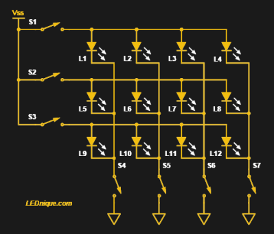 A multiplexing layout for driving LEDs. Source: LEDnique.com
The vast majority of POV displays are built with monochrome LEDs. They’re easy to drive with microcontrollers, with low-power devices requiring just an I/O pin and a current limiting resistor. The simplest displays use a line of LEDs, swept back and forth, or spun around, to generate their images. I’ll talk more about POV displays that move later in this article, but first let’s talk about stationary displays all around us that use the POV effect.
A common trick when trying to drive LEDs is to set them up in an arrangement known as multiplexing. The LEDs are connected in a matrix layout. Anodes are connected in rows, while cathodes are connected in columns. Each row and column is then connected to an IO pin. The tristate nature of IO pins allows the system to work, where each pin can be either high, low, or set to act as a high-impedence input, effectively acting as if disconnected. This arrangement allows 2n pins to drive n2 LEDs, or, for example, 6 pins to drive 9 LEDs. To drive a particular LED, set its row pin high and its corresponding column pin low, while setting the adjacent rows and columns to a high-impedence input state. If you scan the rows of this display fast enough, all of the LEDs will appear to be illuminated thanks to the Persistence of Vision (POV) effect.
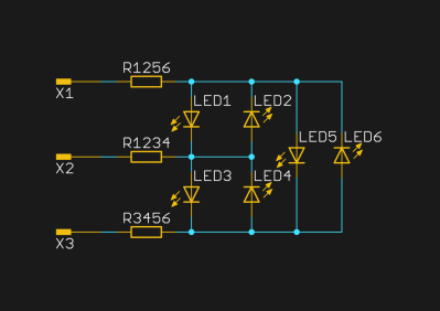 A charlieplexing LED layout. Note the significant increase in complexity over other setups.
If that’s not enough, charlieplexing takes things even further. Between each pair of IO pins, a pair of opposed LEDs is fitted. This arrangement allows n pins to drive n2-n LEDs, or, for example, 6 pins to drive 30 LEDs. What it makes up for in sheer numbers, it pays for in complexity, but if you need to drive a lot of LEDs with few pins, it’s hard to beat. It similarly uses tristates, and relies on the fact that a pair of LEDs in series will have too high a voltage drop to light up, making it possible to control each LED individually.
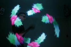 Smart RGB LED strips can take the pain out of driving a lot of LEDs. Plus, full color is always a nice bonus.
Of course, it’s 2019, and the idea of doing a bunch of hard work to drive a handful of monochrome LEDs can seem onerous and boring. Thankfully, technology offers a way out — it’s perfectly possible to simply hook up a smart string of RGB LEDs and use a pre-baked library to drive those instead. RGB LEDs like the WS2811 and WS2812B have their own onboard controllers, and it’s easy to send them commands with their standard interface which just takes a couple of wires. This works without the need for POV, and also has the benefit of providing a wide color gamut, and is well worth considering for a quick and pretty display.
You’ll Wanna Shake ‘Em, Too
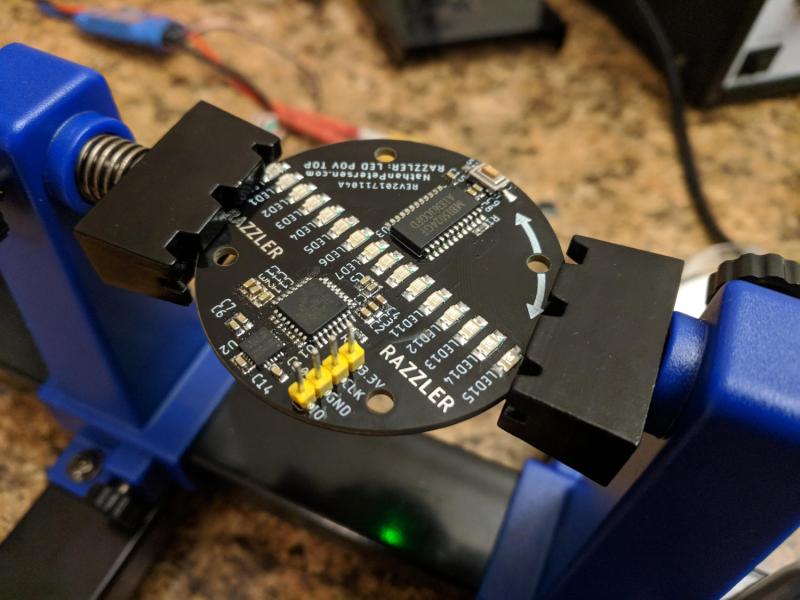 Spinning top POV board built by Nathan Petersen we featured back in December
Now what most people consider a POV display depends on moving some LEDs quickly so that it appears you have many more than actually exists. The pheonomenon discussed above that made all of the LEDs appear to be on at the same time is used here, except a moving LED will appear to be in several places at once. The trick is timing, and so for this arrangement, it is most useful to drive LEDs directly with microcontroller pins rather than use multiplexing techniques.
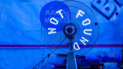 A fan makes an excellent basis for a cool POV project.
You can take a line of LEDs and spin them like the blades of a fan to create the illusion of a full disc of LEDs as the display. Many handheld devices rely on the user shaking the device back and forth. This requires some effort on the individual’s part to get the speed right to display the image properly, but is a quick and dirty method of getting a POV image in the air. Adding an IMU can help with getting the image consistent and straight. But as this waving cat shows, spinning with the addition of a position sensor is the time-tested way of building a stable and readable display. Something as simple as a hall effect sensor and a magnet can do the job nicely.
Spinning POV displays are a very popular build, either in the horizontal or the vertical plane. This creates a display that is either a flat disc, or cylindrical in nature. It’s an easy way to create regular, consistent motion for your POV display. They’re a great addition to bike wheels or a desktop fan. In order to synchronize the display and show a steady image, your microcontroller needs to know when the LEDs arrive back at the beginning of the rotation so the flashing pattern of LEDs synchronizes perfectly with the motion. You have many choices for syncing the display, including a Hall effect sensor and a magnet, an optical sensor, or even a mechanical switch.
Rotating devices can also face issues with power supply — how do you get power to the electronics that are rotating? Smaller projects can often get by with mounting all the electronics, along with a battery, on the rotating mechanism itself. Larger projects often employ slip rings, which allow the passage of power and data signals through a rotating mechanism. With the right design, it’s even possible to take things into the third dimension with this technique, creating a volumetric POV display.
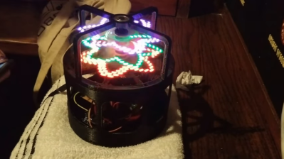 Who said POV displays had to be limited to two dimensions?
Other projects have used alternative methods. We’ve seen flexible PCBs used in combination with magnetic fields to create a flapping display, as well as a 3D-printed reciprocating matrix build. In both cases, the trick is to create a motion that’s fast enough to trigger the persistence of vision effect, and ideally repeatable to create a steady and clear image.
Final Considerations
With the basics of controlling LEDs and motion mastered, you should be well on your way to producing a viable POV display. Other factors can then be considered, such as how to communicate with and control the device, how to create images or messages for the device, or how to make it more robust and reliable in service. These are all engineering challenges that can make the difference between a fun experiment and a useful and exciting display. As you tackle these hurdles in your own builds, keep working away, and if you’ve built something great — be sure to let us know. Happy hacking!
from CommaFeed - Real Time Trends Network https://ift.tt/2Nkkxy5
via IFTTT
Comments
Post a Comment